Iranian Classification Society Rules

< Previous | Contents | Next >
Section 6 Propulsion Machinery
601. Application
The requirements in this Section apply to propulsion machinery covering open- and ducted-type pro- pellers with controllable pitch or fixed pitch design for the Ice classes IA Super, IA, IB, IC and ID. The given loads are the expected ice loads for the whole ship’s service life under normal op- erational conditions, including loads resulting from the changing rotational direction of FP propellers. However, these loads do not cover off-design operational conditions, for example when a stopped propeller is dragged through ice. This requirements also apply to azimuth and fixed thrust- ers for main propulsion, considering loads resulting from propeller-ice interaction. However, the load models in the strength calculation of this Section do not include propeller/ice interaction loads when ice enters the propeller of a turned azimuth thruster from the side (radially) or load case when ice block hits on the propeller hub of a pulling propeller. Ice loads resulting from ice impacts on the
body of thrusters have to able in this Section.
be estimated with suitable methods, but ice load formulae are not avail-
602. Symbols
CP
lim
(kN)
max
FP
(kgm2) LIWL
![]()
(rev./s)
= chord length of blade section (m)
= chord length of blade section at 0.7R propeller radius (m)
= controllable pitch
= propeller diameter (m)
= external diameter of propeller hub (at propeller plane) (m)
= limit value for propeller diameter (m)
= expanded blade area ratio
= maximum backward blade force for the ship’s service life (kN)
= ultimate blade load resulting from blade loss through plastic bending
= maximum forward blade force for the ship’s service life (kN)
= ice load (kN)
= maximum ice load for the ship’s service life (kN)
= fixed pitch
= depth of the propeller centerline from lower ice waterline (m)
= thickness of maximum design ice block entering to propeller (m)
= equivalent mass moment of inertia of all parts on engine side of component under consideration (kgm2)
= equivalent mass moment of inertia of the whole propulsion system
= shape parameter for Weibull distribution
= lower ice waterline (m)
= slope for S-N curve in log/log scale
= blade bending moment (kNm)
= maximum continuous rating
= propeller rotational speed (rev./s)
= nominal propeller rotational speed at in free running condition
![]()
= reference number of impacts per propeller rotational speed per ice class
max
= total number of ice loads on propeller blade for the ship’s service life
= reference number of load for equivalent fatigue stress (10 8 cycles)
= number of propeller revolutions during a milling sequence
= propeller pitch at 0.7R radius (m)
= propeller pitch at 0.7R radius at in free running condition (m)
= propeller pitch at 0.7R radius at in bollard condition (m) Torque
= (kNm)
= maximum engine torque (kNm)
= maximum torque on the propeller resulting from propeller-ice inter action (kNm)
= electric motor peak torque (kNm)
= nominal torque at in free running condition (kNm)
= maximum response torque along the propeller shaft line (kNm)
= maximum spindle torque of the blade for the ship’s service life (kNm)
= propeller radius (m)
= blade section radius (m)
= propeller thrust (kN)
= maximum backward propeller ice thrust for the ship’s service life (kN)
= maximum forward propeller ice thrust for the ship’s service life (kN)
= propeller thrust at in free running condition (kN)
= maximum response thrust along the shaft line (kN)
= maximum blade section thickness (m)
= number of propeller blades
= duration of propeller blade/ice interaction expressed in rotation angle (deg)
= the reduction factor for fatigue; scatter and test specimen size effect
= the reduction factor for fatigue; variable amplitude loading effect
= the reduction factor for fatigue; mean stress effect
= a reduction factor for fatigue correlating the maximum stress amplitude to the equivalent fatigue stress for 108 stress cycles
= proof yield strength of blade material (MPa)
8
= mean fatigue strength of blade material at 10 8 cycles to failure in sea water (MPa)
= equivalent fatigue ice load stress amplitude for 10 stress cycles
![]()
(MPa)
= characteristic fatigue strength for blade
material (MPa)
= reference stress
= reference stress
· ·
(MPa)
= less
· or · · whichever is
= maximum stress resulting from or (MPa)
= ultimate tensile strength of blade material (MPa)
principal stress caused by the maximum backward propeller ice load
= principal stress caused by the maximum forward propeller (MPa)
ice load
= maximum ice load stress amplitude (MPa)
![]()
![]()
Table 1.15 Definition of loads
Definition | Use of the load in design process | |
The maximum backward force on a propeller blade re- sulting from propeller/ice interaction for the ship’s serv- ice life, including hydrodynamic loads on that blade. The direction of the force is perpendicular to 0.7R chord line. See Figure 1.5. | Design force for strength calculation of the propeller blade. | |
The maximum forward force on a propeller blade result- ing from propeller/ice interaction for the ship’s service life, including hydrodynamic loads on that blade. The di- rection of the force is perpendicular to 0.7R chord line. | Design force for calculation of strength of the propeller blade. | |
The maximum spindle torque on a propeller blade result- ing from propeller/ice interaction for the ship’s service life, including hydrodynamic loads on that blade. | In designing the propeller strength, the spindle torque is automatically taken into account be- cause the propeller load is acting on the blade as distributed pressure on the leading edge or tip area. | |
The maximum thrust on propeller (all blades) resulting from propeller/ice interaction for the ship’s service life. The direction of the thrust is the propeller shaft direction and the force is opposite to the hydrodynamic thrust. | Is used for estimation of the response thrust . can be used as an estimate of ex- citation for axial vibration calculations. However, axial vibration calculations are not required in the rules. | |
The maximum thrust on propeller (all blades) resulting from propeller/ice interaction for the ship’s service life. The direction of the thrust is the propeller shaft direction acting in the direction of hydrodynamic thrust. | Is used for estimation of the response thrust . can be used as an estimate of ex- citation for axial vibration calculations. However, axial vibration calculations are not required in the rules. | |
max | The maximum ice-induced torque resulting from pro- peller/ice interaction on one propeller blade, including hydrodynamic loads on that blade. | Is used for estimation of the response torque ( ) along the propulsion shaft line and as excitation for torsional vibration calculations. |
Ultimate blade load resulting from blade loss through plastic bending. The force that is needed to cause total failure of the blade so that plastic hinge is caused to the root area. The force is acting on 0.8R. Spindle arm is to be taken as 2/3 of the distance between the axis of blade rotation and leading/trailing edge (whichever is he greater) at the 0.8R radius. | Blade failure load is used to dimension the blade bolts, pitch control mechanism, propeller shaft, propeller shaft bearing and trust bearing. The objective is to guarantee that total pro- peller blade failure should not cause damage to other components. | |
Maximum response torque along the propeller shaft line, taking into account the dynamic behavior of the shaft line for ice excitation (torsional vibration) and hydro- dynamic mean torque on propeller. | Design torque for propeller shaft line components. | |
Maximum response thrust along shaft line, taking into account the dynamic behavior of the shaft line for ice excitation (axial vibration) and hydrodynamic mean thrust on propeller. | Design thrust for propeller shaft line components. |
![]()
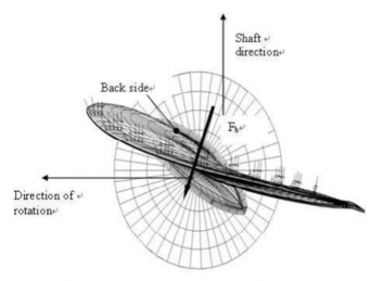
Fig 1.5 Direction of the backward blade force resultant taken perpendicular to chord line at radius 0.7R. (Ice contact pressure at leading edge is shown with small arrows)
603. Design ice conditions
In estimating the ice loads of the propeller for Ice classes, different types of operation as given in
Table 1.16 were taken into account. For the estimation of design ice loads, a maximum size is determined. The maximum design ice block entering the propeller is a rectangular
ice block ice block
with the dimensions
1.17.
· · The thickness of the ice block ( is given in Table
Table 1.16 Type of operation of the ship per Ice classes
Ice class | Operation of the ship |
IA Super | Operation in ice channels and in level ice. The ship may proceed by ramming |
IA, IB, IC, ID | Operation in ice channels |
Table 1.17 The thickness of the ice block (
Ice class | IA Super | IA | IB | IC | ID |
Thickness of the design maximum ice block entering the propeller ( ) | 1.75 m | 1.5 m | 1.2 m | 1.0 m | 1.1 m |
604.
Materials
1. Materials exposed to sea water
Materials of components exposed to sea water, such as propeller blades, propeller hubs, and thruster body, are to have an elongation of not less than 15 % on a test specimen, the gauge length of which is five times the diameter. A Charpy V impact test is to be carried out for mate- rials other than bronze and austenite steel. An average impact energy value of 20 J taken from three tests is to be obtained at minus 10 ºC.
![]()
2. Materials exposed to sea water temperature
Materials exposed to sea water temperature are to be of ductile material. An average impact energy value of 20 J taken from three tests is to be obtained at minus 10 ºC. This requirement applies to blade bolts, CP mechanisms, shaft bolts, strut-pod connecting bolts etc. This does not apply to sur- face hardened components, such as bearings and gear teeth.
605.
Design loads
1. The given loads are intended for component strength calculations only and are total loads including ice-induced loads and hydrodynamic loads during propeller/ice interaction.
2. The values of the parameters in the formulae in this Section is to be given in the units shown in
602.
3. If the propeller is not fully submerged when the ship is in ballast condition, the propulsion system is to be designed according to Ice class IA for Ice classes IB, IC and ID.
4. Design loads on propeller blades
is the maximum force experienced during the ship’s service life that bends a propeller blade backwards when the propeller mills an ice block while rotating ahead. is the maximum force experienced during the ship’s service life that bends a propeller blade forwards when the propeller mills an ice block while rotating ahead. and originate from different propeller/ice interaction phenomena, not acting simultaneously. Hence they are to be applied to one blade separately.
(1) Maximum backward blade force for open
when ≤ lim, · · ·
· (kN)
when lim, · · ·
· · (kN)
where,
lim · (m)
is the nominal rotational speed (at free running condition) for a CP propeller and 85 % of the nominal rotational speed (at free running condition) for a FP propeller.
(2) Maximum forward blade force for open propellers when ≤ lim, · ·
when lim, · · ·
· (kN)
where,
lim · (m).
(3) Loaded area on the blade for open propellers
Load cases 1-4 have to be covered, as given in Table 2.1 of Annex 2, for CP and FP propellers. In order to obtain blade ice loads for a reversing propeller, load case 5 also has to
![]()
be covered for FP propellers.
![]()
(4) Maximum backward blade force for ducted propellers
when ≤ lim, · · · · (kN)
when lim, · · · · ·
(kN)
where,
lim ·
is the nominal rotational speed (at MCR in free running condition) for a CP propeller and 85 % of the nominal rotational speed (at MCR in free running condition) for an FP propeller
(5) Maximum forward blade force for ducted propellers
when ≤ lim,
· (kN)
when lim , · · · (kN)
where,
lim
· (m)
(6) Loaded area on the blade for ducted propellers
Load cases 1 and 3 have to be covered as given in Table 2.2 of Annex 2 for all propellers, and an additional load case (load case 5) for an FP propeller, to cover ice loads when the pro- peller is reversed.
(7) Maximum blade spindle torque for open or ducted propellers
The spindle torque around the axis of the blade fitting is to be determined both for the
maximum backward blade force and forward blade force , which are applied as in Table
2.1 and 2.2 of Annex 2.
If the above method gives a value which is less than the default value given by the formula below, the default value is to be used.
Default Value (kNm)
where,
c0.7 is the chord length of the blade section at 0.7R radius and is either or , whichever has the greater absolute value.
(8) Load distributions for blade loads
The Weibull-type distribution (probability that used for the fatigue design of the blade.
exceeds as given in Fig 1.6, is
≥
max
· ln
where is the shape parameter of the spectrum, is the number of load cycles in the spec- trum, and is the random variable for ice loads on the blade, ≤ ≤ The
![]()
shape parameter = 0.75 is to be used for the ice force distribution of an open propeller blade and the shape parameter = 1.0 for that of a ducted propeller blade.
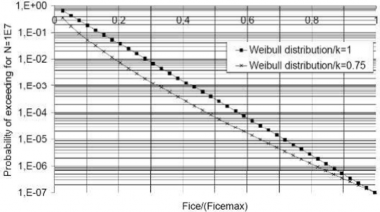
Figure 1.6 The Weibull-type distribution (probability that
that is used for fatigue design.
(Fice exceeds (Fice)max)
(9) Number of ice loads
The number of load cycles per propeller blade in the load spectrum is ing to the formula:
to be determined accord-
· · ·
where,
Reference number of loads for Ice classes
Class | IA Super | IA | IB | IC | ID |
impacts for the ship’s service life / | · | · | · | · | · |
Propeller location factor
Location | Center propeller | Wing propeller |
1 | 1.35 |
![]()
Propeller type factor
type | open | ducted |
1 | 1.1 |
Propulsion type factor
type | fixed | azimuthing |
1 | 1.2 |
The submersion factor k4 is determined from the equation
when
when ≤ ≤
·
when
where the immersion function
where is the depth of the propeller centerline at the lower ice waterline (LIWL) of the ship.
For components that are subject to loads resulting from propeller/ice interaction with all the
propeller blades, the number of load cycles peller blades ( ).
5. Axial design loads for propellers
( is to be multiplied by the number of pro-
(1) Maximum ice thrust on propeller and for propellers The maximum forward and backward ice thrusts are:
· (kN)
(kN)
(2) Design thrust along the propulsion shaft line for propellers
The design thrust along the propeller shaft line is to be calculated with the formulae below. The greater absolute value of the forward and backward direction loads is to be taken as the design load for both directions. The factors 2.2 and 1.5 take into account the dynamic magnifi- cation resulting from axial vibration.
In a forward direction In a backward direction
·
(kN)
If hydrodynamic bollard thrust, , is not known, is to be taken as follows:
![]()
Table 1.18 Propeller bollard thrust
Propeller Type | |
CP propellers (open) | · |
CP propellers (ducted) | · |
FP propellers driven by turbine or electric motor | |
FP propellers driven by diesel engine (open) | · |
FP propellers driven by diesel engine (ducted) | · |
= nominal propeller thrust at MCR at free running open water conditions
6. Torsional design loads
(1) Design ice torque on propeller
max
for open propellers
max
is the maximum torque on a propeller resulting from ice/propeller interaction.
when ≤ lim ,
max
· · · · (kNm)
when
lim ,
max · · · ·
(kNm)
where
lim · (m).
is the rotational propeller speed in bollard condition. If not known, n is to be taken as follows:
Table 1.19 The rotational propeller speed at bollard condition value
Propeller type | Rotational speed |
CP propellers | |
FP propellers driven by turbine or electric motor | |
FP propellers driven by diesel engine | · |
Here, is the nominal rotational speed at MCR in free running condition.
For CP | propellers, propeller pitch, | is to correspond to MCR in bollard condition. If not | |
known, | is to be taken as | · , | is propeller pitch at MCR in free running |
condition.
(2) Design ice torque on propeller
max
for ducted propellers
max
is the maximum torque on a propeller resulting from ice/propeller interaction.
when ≤ lim ,
max ·
· · (kNm)
when
lim ,
max · ·
· · ·
(kNm)
![]()
where
lim · (m)
is the rotational propeller speed in bollard condition. If not known, n is to be taken as follows:
Table 1.20 The rotational propeller speed at bollard condition value
Propeller type | Rotational speed |
CP propellers | |
FP propellers driven by turbine or electric motor | |
FP propellers driven by diesel engine | · |
Here, is the nominal rotational speed at MCR in free running condition.
For CP | propellers, propeller pitch, | is to correspond to MCR in bollard condition. If not | |
known, | is to be taken as | · , | is propeller pitch at MCR in free running |
condition.
(3) Ice torque excitation for propellers
The propeller ice torque excitation for shaft line transient torsional vibration analysis is to be described by a sequence of blade impacts which are of a half sine shape; see Fig 2.1 of Annex 2.
The torque resulting from a single blade ice impact as a function of the propeller rotation angle is then
· max·
when
when
where and parameters are given in table below. is duration of propeller blade/ice
Table 1.21 and parameters
Torque excitation | Propeller-ice interaction | ||
Case 1 | Single ice block | 0.75 | 90 |
Case 2 | Single ice block | 1.0 | 135 |
Case 3 | Two ice blocks (phase shift 360/2/Z deg.) | 0.5 | 45 |
The total ice torque is obtained by summing the torque of single blades, taking into account the phase shift 360deg./Z. In addition, at the beginning and at the end of the milling sequence a linear ramp functions for 270 degrees of rotation angle shall be used.
The number of propeller revolutions during a milling sequence is to be obtained with the for- mula:
·
![]()
The number of impacts is · for blade order excitation.
(4) Design torque along propeller shaft line
If there is not any relevant first blade order torsional resonance within the designed operating rotational speed range extended 20% above the maximum and 20% below the minimum operat- ing speeds, the following estimation of the maximum torque can be used.
max ·
(kNm)
Where, I is equivalent mass moment of inertia of all parts on engine side of component un- der consideration and It is equivalent mass moment of inertia of the whole propulsion sys- tem, all the torques and the inertia moments are to be reduced to the rotation speed of the component being examined.
If the maximum torque, , is not known, it is to be taken as follows:
Table 1.22 the maximum torque
Propeller type | |
Propellers driven by electric motor(FP and CP) | |
CP propellers driven by prime movers other than electric motor | |
FP propellers driven by turbine | |
FP propellers driven by diesel engine | · |
Here, is the electric motor peak torque.
If there is a first blade order torsional resonance within the designed operating rotational speed range extended 20 % above the maximum and 20 % below the minimum operating speeds, the design torque ( ) of the shaft component is to be determined by means of torsional vibration analysis of the propulsion line.
7. Blade failure load
The ultimate load resulting from blade failure as a result of plastic bending around the blade root
is to be calculated with the formula below. The ultimate load radius in the weakest direction of the blade. For calculation spindle arm is to be taken as 2/3 of the distance between the ing/trailing edge (whichever is the greater) at the 0.8 radius.
is acting on the blade at the 0.8 of the extreme spindle torque, the axis of blade rotation and the lead-
ㆍ ㆍ
ㆍ ㆍ (kN)
where,
· ·
, , and are, respectively, the length, thickness, and radius of the cylindrical root section of
![]()
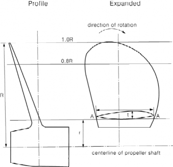
Fig 1.7 Dimension of propeller section for calculation of blade failure load
606. Design
1. Design principle
The strength of the propulsion line is to be designed according to the pyramid strength principle. This means that the loss of the propeller blade shall not cause any significant damage to other pro- peller shaft line components.
2. Propeller blade
(1) Calculation of blade stresses
The blade stresses is to be calculated for the design loads given in Section 605. 4. Finite ele- ment analysis is to be used for stress analysis for final approval for all propellers. The follow-
ing simplified formulae can be used in estimating the blade stresses for all propellers at the root area ( ). The root area dimensions based on following formula can be accepted
even if the FEM analysis would
show greater stresses at the root area.
· · (MPa)
where,
constant is the .
If the actual value is not available, should be taken as 1.6.
· · , for relative radius
is the maximum of and , whichever is greater absolute value.
(2) Acceptability criterion
The following criterion for calculated blade stresses has to be fulfilled.
≥
![]()
where,
is the calculated stress for the design loads. If FEM analysis is used in estimating the stresses, von Mises stresses are to be used.
is the reference stress, defined as:
· or · · , whichever is less.
(3) Fatigue design of propeller blade
The fatigue design of the propeller blade is based on an estimated load distribution for the service life of the ship and the S-N curve for the blade material. An equivalent stress that pro- duces the same fatigue damage as the expected load distribution shall be calculated and the ac- ceptability criterion for fatigue should be fulfilled as given in this Section. The equivalent stress
is normalized for 108 cycles.
If the following criterion is fulfilled, fatigue calculations according to this Section are required.
not
exp ≥ ·
· log
where, , and coefficients for propellers are given in the table below.
Table 1.23 , and coefficients
Open propeller | Ducted propeller | |
0.00270 | 0.00184 | |
1.007 | 1.007 | |
2.101 | 2.470 |
For calculation of equivalent stress two types of S-N curves are available.
- Two slope S-N curve (slopes 4.5 and 10), see Fig 1.8.
- One slope S-N curve( the slope can be chosen), see Fig 1.9.
The type of the S-N curve is to be selected to correspond to the material properties blade. If S-N curve is not known, the two slope S-N curve is to be used.
of the
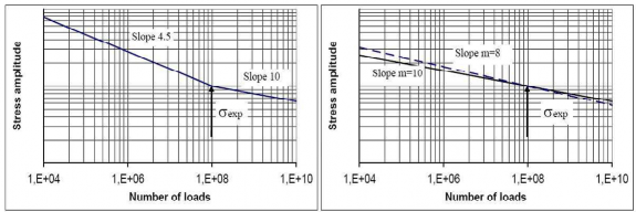
Fig 1.8 Two-slope S-N curve Fig 1.9 Constant-slope S-N curve
(A) Equivalent fatigue stress
The equivalent fatigue stress for 108 stress cycles which produces the same fatigue damage
![]()
as the load distribution is:
·
where,
max
max · max
is the mean value of the principal stress amplitudes resulting from design forward and backward blade forces at the location being studied
is the principal stress resulting from forward load is the principal stress resulting from backward load
In calculation of case 1 and case 3 (or case 2 and case 4) in Table 2.1, 2.2 of Annex 2 are considered as a pair for and calculations. Case 5 is ex- cluded from the fatigue analysis.
(B) Calculation of The parameter
parameter for two-slope S-N curve
relates the maximum ice load to the distribution of ice loads according to
the regression formulae.
· · ·
where,
· · ·
where,
is the reduction factor for scatter and test specimen size effect is the reduction factor for variable amplitude loading
is the reduction factor for mean stress
is the mean fatigue strength of the blade material at 10 8 cycles to failure in
ex
seawater.
The following values should be used for the reduction factors if actual values are not available: = 0.67, = 0.75, and = 0.75.
The coefficients , , , and are given in Table 1.24.
Table 1.24 The coefficients , , , and
Open propeller | Ducted propeller | |
0.000711 | 0.000509 | |
0.0645 | 0.0533 | |
- 0.0565 | - 0.0459 | |
2.22 | 2.584 |
(C) Calculation of parameter for constant-slope S-N curve
For materials with a constant-slope S-N curve(see with the following formula:
Fig 1.9), the factor is to be calculated
![]()
· ln
where,
is the shape parameter of the Weibull distribution = 1.0 for ducted propellers and = 0.75 for open propellers.
is the reference number of load cycles (=10 8)
Values for the parameter are given in Table 1.25.
Linear interpolation may be used to calculate the value for other ratios than given in the Table 1.25.
Table 1.25 Value for the parameter for different ratios
3 | 6 | 5.5 | 287.9 | 8 | 40320 |
3.5 | 11.6 | 6 | 720 | 8.5 | 119292 |
4 | 24 | 6.5 | 1871 | 9 | 362880 |
4.5 | 52.3 | 7 | 5040 | 9.5 | 1.133E6 |
5 | 120 | 7.5 | 14034 | 10 | 3.623E6 |
(4) Acceptability criterion for fatigue
The equivalent fatigue stress at all locations on the blade has to fulfil the following accept- ability criterion.
≥
where,
· ·
where,
is the reduction factor for scatter and test specimen size effect is the reduction factor for variable amplitude loading
is the reduction factor for mean stress
ex is the mean fatigue strength of the blade material at cycles to failure in seawater.
The following values should be used for the reduction factors if actual values are not avail- able: = 0.67, = 0.75, and = 0.75.
3. Propeller bossing and CP mechanism
The blade bolts, the CP mechanism, the propeller boss, and the fitting of the propeller to the pro- peller shaft is to be designed to withstand the maximum and fatigue design loads, as defined in 605. The safety factor against yielding is to be greater than 1.3 and that against fatigue greater than 1.5. In addition, the safety factor for loads resulting from loss of the propeller blade through plastic bending as defined in 605. 7 is to be greater than 1.0 against yielding.
4. Propulsion shaft line
![]()
The shafts and shafting components, and sealings, are to be designed to
such as the thrust and stern tube bearings, couplings, flanges withstand the propeller/ice interaction loads as given in 605.
The safety factor is to be at least 1.3.
(1) Shafts and shafting components
The ultimate load resulting from total blade failure as defined in 605. 7 should not cause yield-
ing in shafts and shaft components. The loading shall consist of the combined axial, bending, and torsion loads, wherever this is significant. The minimum safety factor against yielding is to be 1.0 for bending and torsional stresses.
5. Azimuth main propulsors
In addition to the above requirements, special consideration is to be given to those loading cases which are extraordinary for propulsion units when compared with conventional propellers. The esti- mation of loading cases has to reflect the way of operation of the ship and the thrusters. In this respect, for example, the loads caused by the impacts of ice blocks on the propeller hub of a pull- ing propeller have to be considered. Furthermore, loads resulting from the thrusters operating at an oblique angle to the flow have to be considered. The steering mechanism, the fitting of the unit, and the body of the thruster are to be designed to withstand the loss of a blade without damage. The loss of a blade is to be considered for the propeller blade orientation which causes the max- imum load on the component being studied. Typically, top-down blade orientation places the max- imum bending loads on the thruster body.
Azimuth thrusters are to also be designed for estimated loads caused by thruster body/ice interaction. The thruster body has to stand the loads obtained when the maximum ice blocks, which are given in 603., strike the thruster body when the ship is at a typical ice operating speed. In ad- dition, the design situation in which an ice sheet glides along the ship’s hull and presses against the thruster body should be considered. The thickness of the sheet should be taken as the thickness of the maximum ice block entering the propeller, as defined in 603.
6. Vibrations
The propulsion system is to be designed in such a way that the complete dynamic system is free from harmful torsional, axial, and bending resonances at a 1-order blade frequency within the de- signed running speed range, extended by 20 percent above and below the maximum and minimum operating rotational speeds. If this condition cannot be fulfilled, a detailed vibration analysis has to be carried out in order to determine that the acceptable strength of the components can be achieved.
607. Alternative design procedure
1. Scope
As an alternative to 605. and 606., a comprehensive design study may be carried out to the sat- isfaction of the society. The study has to be based on ice conditions given for different Ice classes in 603. It has to include both fatigue and maximum load design calculations and fulfil the pyramid strength principle, as given in 606. 1.
2. Loading
Loads on the propeller blade and propulsion system are to be based on an acceptable estimation of hydrodynamic and ice loads.
3. Design levels
(1) The analysis is to indicate that all components transmitting random (occasional) forces, excluding propeller blade, are not subjected to stress levels in excess of the yield stress of the component material, with a reasonable safety margin.
(2) Cumulative fatigue damage calculations are to indicate a reasonable safety factor. Due account is to be taken of material properties, stress raisers, and fatigue enhancements.
(3) Vibration analysis is to be carried out and is to indicate that the complete dynamic system is free from harmful torsional resonances resulting from propeller/ice interaction.
![]()